A panel schedule can look complete and still fail at handover. The consultant writes an absorption figure, the contractor fixes the panels flat to preserve a few centimetres of usable room, and the space passes its visual inspection. Then the client reports that it still booms in the bass, and nobody can agree whether the product or the installation is at fault. The schedule specified a number but never described the mounting. In porous-absorber acoustics the air behind the panel is part of the product: acoustic panel air gap absorption is what turns a thin, mid-band-only finish into a treatment that works in the frequency ranges where rooms actually struggle. Specify the cavity as carelessly as the facing and you buy the appearance of absorption rather than the performance.
This guide is for the people who sign off the specification and the installation: acoustic consultants, architects, main contractors, distributors and procurement managers. It explains how laboratory mounting codes work, how air depth relates to the frequency you need to treat, how to choose the backing felt or infill that makes the gap effective, and what to put in an RFQ and submittal so the number on the data sheet matches the condition you build. All depths and frequency ranges here are indicative planning guidance; performance for your project must come from test data at the intended mounting and be confirmed in the formal quotation.
Acoustic panel air gap absorption begins with the mounting code
Absorption coefficients are not properties of a panel alone. They are properties of a panel in a specific mounting condition, measured in a reverberation chamber to a standard such as ISO 354 or ASTM C423. The code printed beside the data is therefore as important as the number. In the convention used across many supplier reports, Type A means the panel is fixed directly to a reflective wall with no airspace; codes such as Type D describe panels on battens creating a modest cavity; and E-200 or E-400 denote a panel mounted with a roughly 200 mm or 400 mm air gap in front of a reflective backing. Mounting type E-400 is not a product name. It is a test condition, and a specifier who reads it as a feature is asking for trouble.
Two consequences follow. First, a panel quoted with a curve measured at E-400 will not reproduce that curve on 25 mm battens, even though it is physically the same panel. Second, a product advertised with a single NRC measured direct-fixed may still be an excellent cavity absorber; the brochure simply does not show it. When you compare quotations, insist on per-frequency absorption coefficients with the mounting condition stated, and reject any comparison that mixes mounting codes. Ask the supplier to state the mounting used for every figure they quote, and to provide data for the mounting you will actually build. If the design uses a 50 mm batten cavity, a report measured at 200 mm is useful background but not evidence for your room. Where the built condition falls between published depths, let the acoustic consultant interpret the data rather than interpolating a number by eye.
How the cavity shifts absorption towards low frequencies
A porous absorber works because air oscillates through its fibres and loses energy to friction. Close to a hard reflective wall the air particles barely move; roughly a quarter wavelength away they move fastest. Glue a thin panel directly to masonry and its fibres sit in that slow-air zone, so they contribute little at low frequencies. Stand the same panel off the wall and the high-velocity zone moves into the material. The panel-plus-cavity behaves as a resistive layer in front of an air spring, and the useful low-frequency limit falls as the combined thickness of absorber and air increases. This is the mechanism behind room-by-room acoustic treatments that must address bass as well as speech.
A common first-order guide is f approximately equal to c divided by four times (t plus d), where t is absorber thickness, d is the air gap and c is the speed of sound. Use it to reason about direction, not as a design formula: real results depend on flow resistivity, facing porosity, cavity division and the room itself. The practical message is robust. Deepening the gap moves the benefit downward, and returns diminish once the gap is large relative to the absorber unless the cavity contains a suitable porous layer. An empty void sealed behind an impervious facing behaves as a resonator, not a broad absorber. Slatted and perforated panels only work acoustically because their openings let sound reach felt or mineral wool behind them.
Cavity depth selection: an indicative table
The table is a starting point for discussion, not a specification. It maps common mounting depths to the band where an effect is normally seen and to the project types where each is considered. Replace every indicative figure with the supplier’s measured data for the exact build-up, and confirm the depth is achievable within the wall or ceiling build.
| Mounting condition | Indicative air gap | Indicative low-frequency benefit | Where it is normally considered |
|---|---|---|---|
| Direct fixed (Type A) | 0 mm | Speech band and above; limited below about 250 Hz | Corridors, shallow walls, budget direct-stick programmes |
| Shallow batten | Approx. 25 mm | Useful change from roughly 250-500 Hz | Retrofit where depth is tight and reveals are fixed |
| Standard batten | Approx. 40-50 mm | Common commercial sweet spot; measurable below 250 Hz | Offices, classrooms, meeting rooms |
| Deep cavity | Approx. 100 mm | Low-frequency control; diminishing returns for thin facings | Auditoria, music rooms, plant rooms |
| Type E-200 | Approx. 200 mm | Tested low-band performance; needs documented data | Performance-specified spaces with model inputs |
| Type E-400 | Approx. 400 mm | Deep-cavity condition; specialist design and data | Studios, critical listening rooms, large-volume halls |
Depth is never free. It consumes floor area, changes skirtings and door reveals, and must be coordinated with the fire strategy for the wall or ceiling. A 400 mm cavity is a design decision involving the structural and services teams, not a line the acoustician can add late without consequence.
Backing felt air cavity: choosing the layer behind the panel
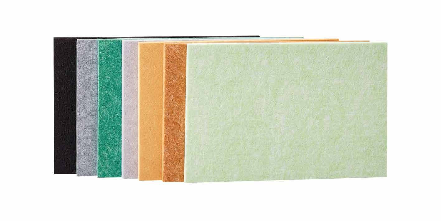
The gap does not absorb on its own. The material inside it, or directly in front of it, supplies the flow resistance that turns particle motion into heat. For a felt-backed slat panel the backing felt is that layer: its areal density and thickness set the resistance. Too open and sound passes through with little loss; too dense and the layer begins to reflect rather than absorb. Indicative commercial felt backings sit around 9-15 mm in slat assemblies, while standalone PET felt panels are commonly supplied at 9, 12 or 24 mm. The right choice is the one supported by measured data for the finished construction, not the thickest option on the price list.
Mineral wool and PET felt behave differently and both are legitimate. Light, open mineral wool offers high porosity per unit thickness and is often used where a deep cavity can be lightly filled. PET felt is rigid, self-supporting and dimensionally stable, which suits exposed slat backings and demountable assemblies. What matters acoustically is flow resistivity and how the layer is coupled to the gap, not the marketing label. A lightly filled cavity can extend the low-frequency benefit; packing it densely can short-circuit the air spring and reduce the very effect you are paying for. Ask for the section drawing that shows facing, backing and cavity as one assembly. The PET polyester acoustic panel range and the custom colour acoustic felt panel illustrate standard backing options, while the glass-fibre ceiling panel category covers the wool-based alternative.
The choice between felt and wool should be traceable to the test report for the assembly. Lightweight mineral wool is one option for a filled cavity; the technical catalogue summarises the standard backing options available.
Application scenarios: where the gap earns its depth
- Open-plan offices: a modest 40-50 mm cavity behind felt panels can improve low frequency absorption where speech privacy and HVAC noise overlap, without losing significant floor area.
- Education and meeting rooms: cavity mounting helps when reverberation targets must be met across the speech band and the first octave below it; pair the detail with a ceiling strategy for best effect.
- Plant rooms and equipment spaces: deeper cavities and lightweight infill target tonal low-frequency energy that direct-fixed panels cannot reach.
- Auditoria and music rooms: model the room, then select the mounting whose measured data feeds the model; a Type E-400 figure used on a shallow wall will invalidate the prediction.
- Shallow corridors and refurbishment: where depth genuinely is unavailable, accept direct fixing, specify a thicker absorber, and do not claim low-frequency performance the construction cannot deliver.
In every case the acoustic and dimensional decisions are linked. Changing the gap changes the result; so does dividing the cavity with dense blocking or filling it with services. Resolve both in the same drawing set.
RFQ checklist for acoustic panel air gap absorption
A precise enquiry gets comparable answers. Include the following and require a written response to each item before you shortlist.
- Project location, room volume and the reverberation or intelligibility target you are trying to meet.
- Panel construction: facing type, perforation or slat open area, backing material, backing thickness and areal density.
- Intended mounting: direct fix, stated batten depth, or a named laboratory condition such as E-200 / E-400, with the as-built depth shown on a section.
- Per-frequency absorption coefficients measured at that mounting, with test standard, laboratory and report reference.
- Cavity details: batten spacing, whether the void is filled, fill density, and how perimeter edges are treated.
- Fire classification for the complete assembly as installed, including the cavity treatment and any infill.
- Service coordination: cabling, ducts or pipework passing through the cavity and who is responsible for keeping it continuous.
- Area, fixing system, substrate preparation responsibility, assembly weight, and the tolerance and spare-panel policy.
Send the package through the contact page and keep the technical catalogue alongside it as the reference for standard backings and fixings. Ask for the mounting condition to be written into the quotation, not agreed verbally after the order.
Common mistakes in acoustic panel air gap absorption detailing
- Quoting data from the wrong mounting: an E-400 curve applied to a 25 mm batten wall is a claim the built room cannot honour.
- Sealing the cavity perimeter: continuous adhesive blobs around the panel edge short-circuit the gap; preserve the open path unless the detail is deliberately a sealed system.
- Over-filling the void: dense packing reflects sound and wastes the air spring; “light and open” is usually the correct instruction.
- Dividing the cavity: services, blocking and closely spaced studs can fragment the air volume behind the treated area.
- Hiding an impermeable layer: a protective film or closed-cell backing on the rear of a perforated facing makes the assembly acoustically sealed.
- Ignoring fire and access: a cavity that crosses a fire compartment line, or one that hides services needing maintenance, needs an early coordinated detail.
- Specifying by thickness alone: without density, backing and mounting, two visually identical panels are not comparable products.
Specify the cavity with the same care as the panel
The reliable sequence is simple: agree the target frequency band, select a mounting whose measured data covers it, choose a backing layer that makes the gap work, then draw the cavity and coordinate it with structure, services and fire. MST Acoustics supplies felt, slat, grooved and mineral-fibre acoustic panels with documented build-ups, and our technical team can check a cavity detail against the intended mounting before manufacture. Request a quote with your section drawing and mounting requirement, or download the catalogue to shortlist backings and finishes. All values in this guide are indicative planning guidance; final dimensions, performance data, tolerances and commercial terms must be confirmed in the formal quotation.
Frequently asked questions
What is acoustic panel air gap absorption?
It is the improvement in absorption that comes from mounting a porous panel away from a reflective surface, so the air cavity becomes part of the acoustic system. The gap shifts useful absorption towards lower frequencies; the backing felt or infill supplies the flow resistance that converts particle movement into heat. The benefit depends on the exact mounting, not on the panel alone.
What does mounting type E-400 mean on a test report?
It describes a laboratory mounting condition in which the panel is tested with an approximately 400 mm air gap in front of a reflective backing. It is a test setup, not a product grade. Data measured at E-400 cannot be claimed for a panel fixed on 25 or 50 mm battens; always match the report’s mounting to the as-built cavity before using the figures.
How much air gap do I need behind acoustic panels?
As indicative guidance, 40-50 mm behind a 12-24 mm felt panel is a common commercial compromise, giving measurable low-frequency benefit with little loss of room depth. Deeper cavities around 100 mm and beyond are used when bass control dominates, but returns diminish unless the void is lightly filled. Confirm the figure with measured data for your construction.
Can I use E-200 or E-400 absorption data for a shallow batten installation?
No. Those figures describe deep-cavity test conditions. Applying them to a shallow installation overstates low-frequency performance and can invalidate a reverberation model. Ask the supplier for coefficients measured at the mounting you will build, or have the consultant interpret data from the nearest published condition.
Should the cavity be filled with felt or mineral wool?
Not always. An empty but open cavity can still help, and a lightly placed porous infill can extend the low-frequency benefit. Dense packing can short-circuit the air spring and reduce absorption. Where the facing is slatted or perforated, the backing felt behind it is often the working absorber; the fill decision should follow the tested assembly.
What documents should I request for a cavity-mounted panel system?
Request a dimensioned section showing facing, backing and air depth; per-frequency absorption coefficients with the test standard, laboratory and mounting condition; the fire classification of the complete assembly as installed; cavity and infill details; and written confirmation of area, fixing, tolerances and batch policy. Require the mounting condition to appear on the quotation.